Whether you’re designing AC-DC or DC-DC power supplies from scratch or you’re digging into an existing design, you’re probably looking to minimize switching loss. The losses in MOSFETs and IGBTs during transitions and conduction have a significant impact on power supply efficiency. Understanding any variation between the expected power dissipation, based on component specifications, and actual performance is critical to ensuring the best efficiency in a design.
Oscilloscopes are well-suited for making these measurements since they allow you to quantify switch performance in-circuit. This has the advantage of taking into account all of the parasitics, including not only the capacitance, inductance and resistance within the MOSFET or IGBT, but also the PCB traces and surrounding components.

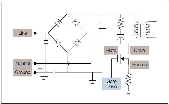
Measuring switching loss in-circuit, during operation, takes into account parasitic effects in traces and surrounding components.
It takes a capable oscilloscope to make the measurements, but a number of oscilloscopes have the right features for measuring switching loss, namely:
- Compatible differential voltage and current probes
- Ability to correct delay between voltage and current channels (deskew)
- Waveform multiplication
- Measurement gating
- Measurement of the arithmetic mean
It also helps to have filtering and averaging capability to deal with noise. It’s easy to forget to compensate for the channel to channel delay between voltage and current channels. This is called “deskew” and forgetting to compensate the system for delay will cause your power measurement results to be incorrect. You’ll have to make sure you use the full dynamic range of the instrument for the best measurement resolution. And finally, remember to gate the measurements with cursors and keep the cursors in roughly the same locations each time you measure. The application note “Measuring Power Supply Switching Loss with an Oscilloscope” gives a breakdown of these measurements.
As long as you’re very rigorous and consistent, and ensure that others who may be making measurements are equally disciplined, you will be able to measure switching loss with good results.
However, this level of rigor isn’t always easy to maintain, especially when a project milestone is looming. And most of us aren’t measuring switching loss every day, so relying on memory can be a risky proposition.

Switching device voltage and current are acquired, multiplied and the mean is taken over each section of a complete cycle, to determine turn-on, turn-off, as well as conduction loss.
Power Analysis Software Delivers Fast, Consistent Measurements
Rather than rely on written procedures or memory to get reliable switching loss measurements, power analysis software that runs on your scope can automate the process. The software handles a lot of the setup and analysis, greatly increasing the repeatability of measurements:
- Optimizes the scope scaling to make the best use of dynamic range
- Provides automated support for probe deskew
- Analyzes the resulting waveforms to give turn-on loss, turn-off loss and conduction loss in a single table.

Automated switching loss measurements using DPOPWR Power Analysis software on an MSO5000 Series Oscilloscope
The application note, “Measuring Power Supply Switching Loss with an Oscilloscope” gives additional switching loss measurement examples using the DPOPWR Power Analysis software package. DPOPWR software runs on MSO/DPO5000 Series Oscilloscopes and performs many measurements in addition to switching loss - the DPOPWR Power Analysis Software datasheet, give the details. Power analysis software is also available on the MDO/MSO/DPO4000 Series, MDO3000 Series, and MSO/DPO3000 Series, as well as the TPS2000 Series.
Since publishing the above blog, Tektronix is currently offering a free upgrade to 3/6 GHz spectrum analyzers and a free bundle of software applications on mixed-domain oscilloscopes.